Last year, we had to configure C-series servers to boot from an FC storage array. In this post, we will try to reproduce some of the complicated production environment topologies, however, in a simplified version. Therefore, we will demonstrate a basic configuration to boot a C-series server from a remote storage according to the topology shown below.
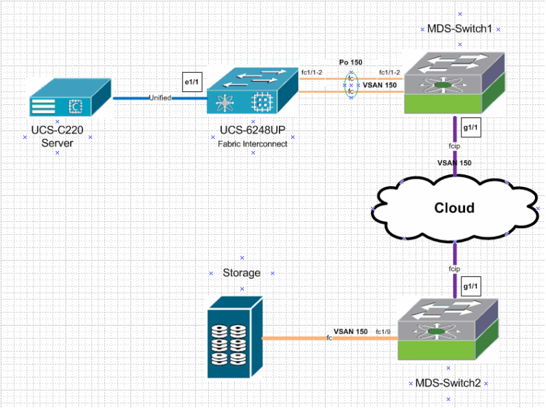
As stated above that configurations and topologies are simplified but they are still CCIE level. A basic understanding of Native Fiber Channel, Fiber Channel over IP, WWPN, WWNN, basic UCS and basic storage is recommended. We will try to cover the configuration of links/Port-channels that fall in between the UCS server and storage in detail. Nevertheless, a Service Profile needs to be configured on the Fabric Interconnect (this will be covered in another Post as it includes so many steps). For simplicity, we will cover only the required steps to associate a service profile with our target server.
Step 1: FC link configuration toward Storage
We will configure the Fiber channel link between the Storage array and MDS-Switch2. The configuration of the storage array is out of scope for this Post. In addition we will configure the Zoning in a later step, which is a kind of filter or access-list for fiber channel protocol.
On MDS-Switch2 : we will configure vsan 150, change the interface fc1/9 vsan membership and check the registration of the Array.
vsan database
vsan 150
vsan 150 interface fc1/9
int fc1/9
no shut
MDS-SWitch2# show flogi database
--------------------------------------------------------------------------------
INTERFACE VSAN FCID PORT NAME NODE NAME
--------------------------------------------------------------------------------
fc1/9 150 0x1601d5 22:00:00:11:c6:0c:50:1c 20:00:00:11:c6:0c:50:1c
Total number of flogi = 1.
Step2: FCIP link Configuration
To configure the FCIP link between MDS-Switch2 and MDS-Switch1, we will use fcip profile 15 on both switches and subnet 10.10.10.0/30 for the link in between. In addition to the FCIP Feature to be enabled on both MDS switches, we need to accommodate the MTU size over the FCIP link to support the size of a Native FC frame > 2300.
On MDS-Switch2:
feature fcip
int g1/1
ip add 10.10.10.1 255.255.255.252
switchport mtu 3000
no shut
fcip profile 15
ip address 10.10.10.1
interface fcip15
use-profile 15
peer-info ipaddr 10.10.10.2
switchport trunk allowed vsan 150
no shutdown
On MDS-Switch1:
vsan database
vsan 150
feature fcip
int g1/1
ip add 10.10.10.2 255.255.255.252
switchport mtu 3000
no shut
fcip profile 15
ip address 10.10.10.2
interface fcip15
use-profile 15
peer-info ipaddr 10.10.10.1
switchport trunk allowed vsan 150
no shutdown
Step3: check the FCIP link status
Check the status of the fcip15 interface on both MDS switches.
MDS-Switch1(config-if)# show int fcip 15
fcip15 is trunking
Hardware is GigabitEthernet
Port WWN is 20:14:00:05:73:b0:a2:00
Peer port WWN is 20:14:00:0d:ec:6c:9c:00
Admin port mode is auto, trunk mode is on
snmp link state traps are enabled
Port mode is TE
Port vsan is 1
Speed is 1 Gbps
Trunk vsans (admin allowed and active) (150)
Trunk vsans (up) (150)
Trunk vsans (isolated) ()
Trunk vsans (initializing) ()
MDS-SWitch2(config-if)# show int fcip 15
fcip15 is trunking
Hardware is GigabitEthernet
Port WWN is 20:14:00:0d:ec:6c:9c:00
Peer port WWN is 20:14:00:05:73:b0:a2:00
Admin port mode is auto, trunk mode is on
snmp link state traps are enabled
Port mode is TE
Port vsan is 1
Speed is 1 Gbps
Trunk vsans (admin allowed and active) (150)
Trunk vsans (up) (150)
Trunk vsans (isolated) ()
Trunk vsans (initializing) ()
Step4: Port-Channel 150 configuration
Fabric-Interconnects are usually meant to be configured in end host mode with NPV (Node Port Virtualization). In this case, the other end (MDS-Swich1) needs to be configured in NPIV mode.
On MDS-Switch1
feature npiv
feature fport-channel-trunk
int fc1/1-2
switchport mode f
channel-group 150
no shut
interface port-channel 150
channel mode active
switchport mode F
switchport trunk allowed vsan 150
switchport rate-mode shared
On Fabric Interconnect
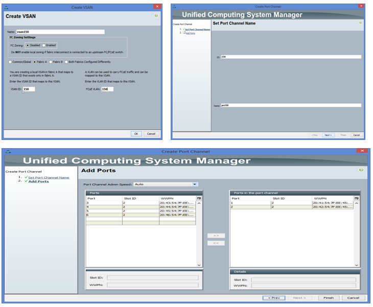
First we need to create vsan 150 then port-channel 150
Step 1: FC link configuration toward Storage
We will configure the Fiber channel link between the Storage array and MDS-Switch2. The configuration of the storage array is out of scope for this Post. In addition we will configure the Zoning in a later step, which is a kind of filter or access-list for fiber channel protocol.
On MDS-Switch2 : we will configure vsan 150, change the interface fc1/9 vsan membership and check the registration of the Array.
vsan database
vsan 150
vsan 150 interface fc1/9
int fc1/9
no shut
MDS-SWitch2# show flogi database
--------------------------------------------------------------------------------
INTERFACE VSAN FCID PORT NAME NODE NAME
--------------------------------------------------------------------------------
fc1/9 150 0x1601d5 22:00:00:11:c6:0c:50:1c 20:00:00:11:c6:0c:50:1c
Total number of flogi = 1.
Step2: FCIP link Configuration
To configure the FCIP link between MDS-Switch2 and MDS-Switch1, we will use fcip profile 15 on both switches and subnet 10.10.10.0/30 for the link in between. In addition to the FCIP Feature to be enabled on both MDS switches, we need to accommodate the MTU size over the FCIP link to support the size of a Native FC frame > 2300.
On MDS-Switch2:
feature fcip
int g1/1
ip add 10.10.10.1 255.255.255.252
switchport mtu 3000
no shut
fcip profile 15
ip address 10.10.10.1
interface fcip15
use-profile 15
peer-info ipaddr 10.10.10.2
switchport trunk allowed vsan 150
no shutdown
On MDS-Switch1:
vsan database
vsan 150
feature fcip
int g1/1
ip add 10.10.10.2 255.255.255.252
switchport mtu 3000
no shut
fcip profile 15
ip address 10.10.10.2
interface fcip15
use-profile 15
peer-info ipaddr 10.10.10.1
switchport trunk allowed vsan 150
no shutdown
Step3: check the FCIP link status
Check the status of the fcip15 interface on both MDS switches.
MDS-Switch1(config-if)# show int fcip 15
fcip15 is trunking
Hardware is GigabitEthernet
Port WWN is 20:14:00:05:73:b0:a2:00
Peer port WWN is 20:14:00:0d:ec:6c:9c:00
Admin port mode is auto, trunk mode is on
snmp link state traps are enabled
Port mode is TE
Port vsan is 1
Speed is 1 Gbps
Trunk vsans (admin allowed and active) (150)
Trunk vsans (up) (150)
Trunk vsans (isolated) ()
Trunk vsans (initializing) ()
MDS-SWitch2(config-if)# show int fcip 15
fcip15 is trunking
Hardware is GigabitEthernet
Port WWN is 20:14:00:0d:ec:6c:9c:00
Peer port WWN is 20:14:00:05:73:b0:a2:00
Admin port mode is auto, trunk mode is on
snmp link state traps are enabled
Port mode is TE
Port vsan is 1
Speed is 1 Gbps
Trunk vsans (admin allowed and active) (150)
Trunk vsans (up) (150)
Trunk vsans (isolated) ()
Trunk vsans (initializing) ()
Step4: Port-Channel 150 configuration
Fabric-Interconnects are usually meant to be configured in end host mode with NPV (Node Port Virtualization). In this case, the other end (MDS-Swich1) needs to be configured in NPIV mode.
On MDS-Switch1
feature npiv
feature fport-channel-trunk
int fc1/1-2
switchport mode f
channel-group 150
no shut
interface port-channel 150
channel mode active
switchport mode F
switchport trunk allowed vsan 150
switchport rate-mode shared
On Fabric Interconnect
First we need to create vsan 150 then port-channel 150
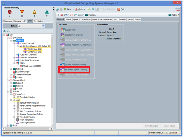
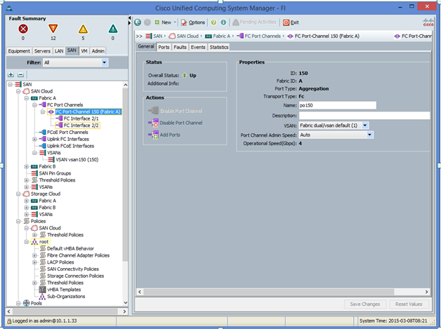
on the fabric interconnect, we need enable FC-port truning and then check the port-channel 150 is up
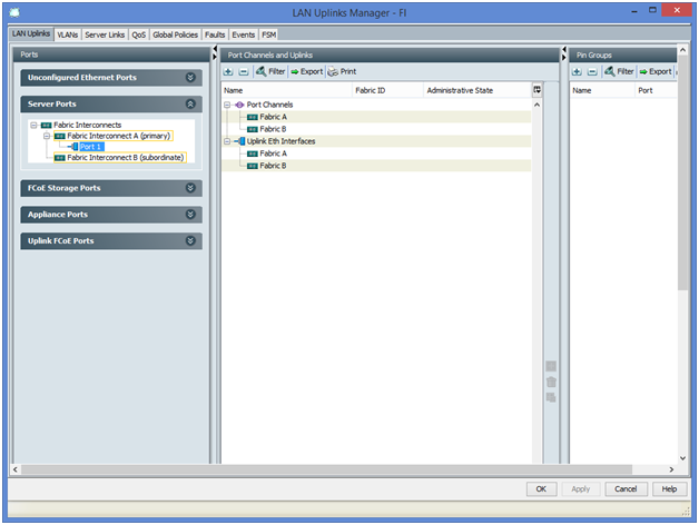
Step5: Unified link Configuration
Now we need to configure the Link between Fabric interconnect and C-series servers as server Port
Now we need to configure the Link between Fabric interconnect and C-series servers as server Port
Step6: Resources allocation
We will configure the UUID, WWPN, WWNN and MAC pools
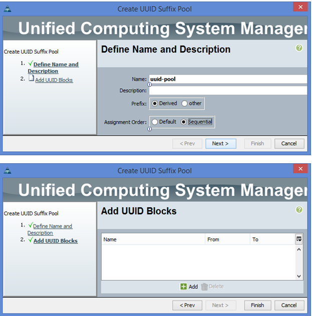
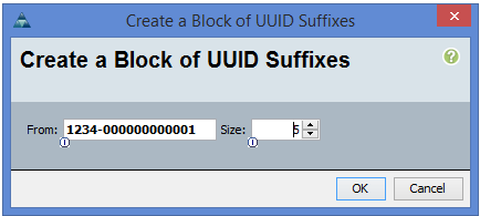
UUID Pool Creation
In UCSM under Servers-> pools -> root -> UUID Suffix pools -> right mouse button -> Create new pool
We will configure the UUID, WWPN, WWNN and MAC pools
UUID Pool Creation
In UCSM under Servers-> pools -> root -> UUID Suffix pools -> right mouse button -> Create new pool
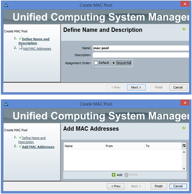
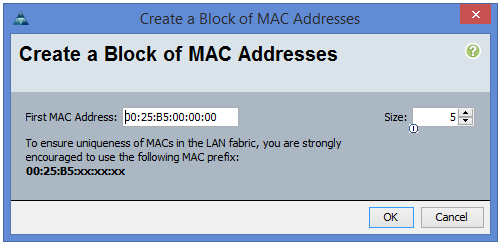
MAC Pool Creation
In UCSM under LAN -> pools -> root -> MAC pools -> mouse right button -> create MAC pool
In UCSM under LAN -> pools -> root -> MAC pools -> mouse right button -> create MAC pool
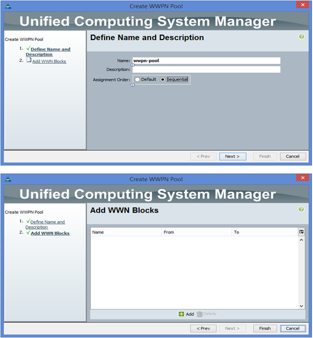
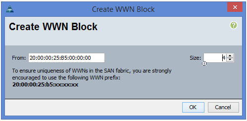
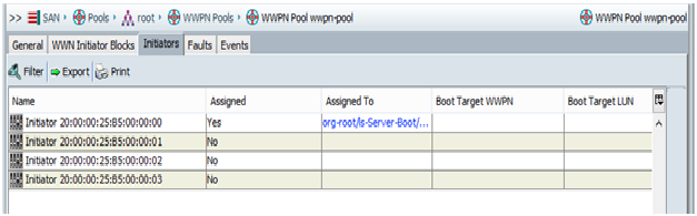
WWPN Pool Creation
In UCSM under SAN -> pools -> root -> WWPN pools -> mouse right click -> Create WWPN pool
In UCSM under SAN -> pools -> root -> WWPN pools -> mouse right click -> Create WWPN pool
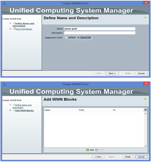
WWNN Pool creation
In UCSM under SAN -> pools -> root -> WWNN pools -> mouse right click -> Create WWNN pool
In UCSM under SAN -> pools -> root -> WWNN pools -> mouse right click -> Create WWNN pool

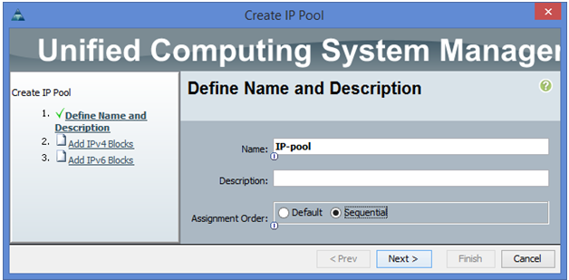
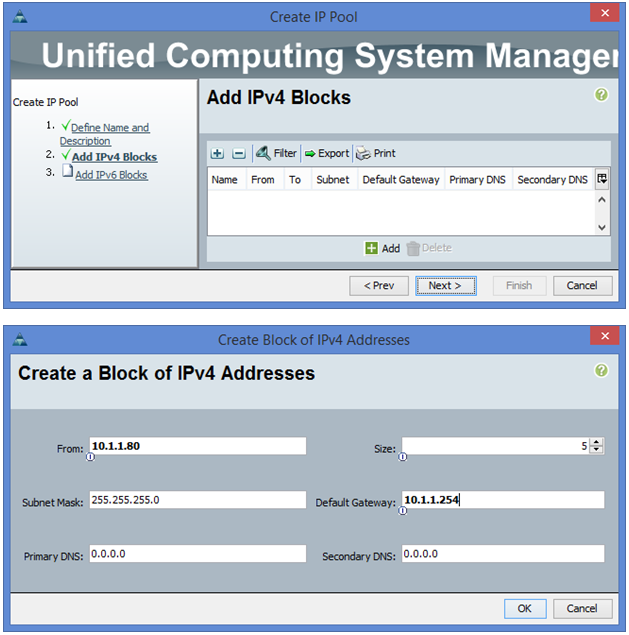
IP pool Creation for KVM
In UCSM under LAN -> pools -> root -> IP pools -> mouse right button -> create IP pool
In UCSM under LAN -> pools -> root -> IP pools -> mouse right button -> create IP pool
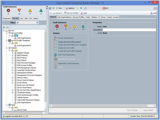
Step 7: Service Profile Configuration
Now we need to configure the Profile that needs to be associated with the C-series server.
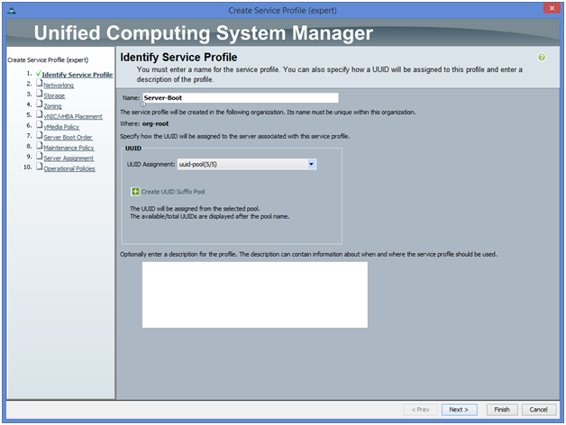
Under UCSM server tab -> Service profile, we choose the expert mode for Service Profile creation
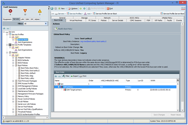
Note: The service Profile creation is not fully covered in this post (will be covered in a future post) However, the most important configurations are shown; like Boot policy
We give server-boot as the name of service profile
The boot policy to be linked to the service profile should point to the WWNP of the storage array assuming the LUN0 configured by default.
Step 8: configure Zoning on MDS-Switch2
Adding the 4 WWPNs created in step6/WWPN pool creation to the zone name “zone_vsan150” under zoneset name “zoneset_vsan150” in addition to WWPN of the storage configured in step1 that shows under show flogi database command.
MDS-SWitch2(config-if)# zoneset name zoneset_vsan150 vsan 150
MDS-SWitch2(config-zoneset)# zone name zone_vsan150
MDS-SWitch2(config-zoneset-zone)# member pwwn 22:00:00:11:c6:0c:50:1c
MDS-SWitch2(config-zoneset-zone)# member pwwn 20:00:00:25:B5:00:00:00
MDS-SWitch2(config-zoneset-zone)# member pwwn 20:00:00:25:B5:00:00:01
MDS-SWitch2(config-zoneset-zone)# member pwwn 20:00:00:25:B5:00:00:02
MDS-SWitch2(config-zoneset-zone)# member pwwn 20:00:00:25:B5:00:00:03
MDS-SWitch2(config-zoneset-zone)# zoneset activate name zoneset_vsan150 vsan 150
Zoneset activation initiated. check zone status
##### The active zoneset should be propagated to MDS-Switch2
MDS-Switch1# show zoneset active
zoneset name zoneset_vsan150 vsan 150
zone name zone_vsan150 vsan 150
* fcid 0x1601d5 [pwwn 22:00:00:11:c6:0c:50:1c]
pwwn 20:00:00:25:b5:00:00:00
pwwn 20:00:00:25:b5:00:00:01
pwwn 20:00:00:25:b5:00:00:02
pwwn 20:00:00:25:b5:00:00:03
Step 9: Service profile assignment to the server
MDS-SWitch2(config-zoneset)# zone name zone_vsan150
MDS-SWitch2(config-zoneset-zone)# member pwwn 22:00:00:11:c6:0c:50:1c
MDS-SWitch2(config-zoneset-zone)# member pwwn 20:00:00:25:B5:00:00:00
MDS-SWitch2(config-zoneset-zone)# member pwwn 20:00:00:25:B5:00:00:01
MDS-SWitch2(config-zoneset-zone)# member pwwn 20:00:00:25:B5:00:00:02
MDS-SWitch2(config-zoneset-zone)# member pwwn 20:00:00:25:B5:00:00:03
MDS-SWitch2(config-zoneset-zone)# zoneset activate name zoneset_vsan150 vsan 150
Zoneset activation initiated. check zone status
##### The active zoneset should be propagated to MDS-Switch2
MDS-Switch1# show zoneset active
zoneset name zoneset_vsan150 vsan 150
zone name zone_vsan150 vsan 150
* fcid 0x1601d5 [pwwn 22:00:00:11:c6:0c:50:1c]
pwwn 20:00:00:25:b5:00:00:00
pwwn 20:00:00:25:b5:00:00:01
pwwn 20:00:00:25:b5:00:00:02
pwwn 20:00:00:25:b5:00:00:03
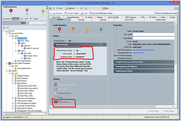
Step 9: Service profile assignment to the server
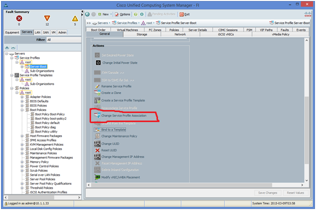
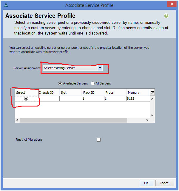
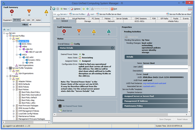
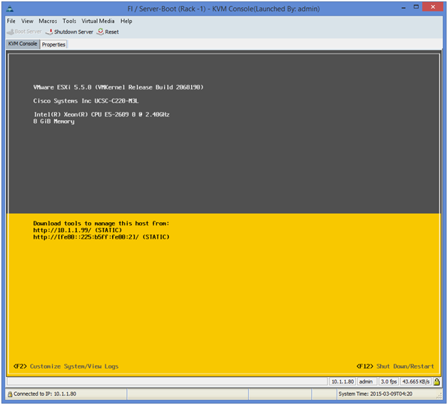
Once the C-series server is associated (you can check the progress bar under FSM tab) you can monitor the server boot from the KVM windows that pops up if the KVM Console is requested.
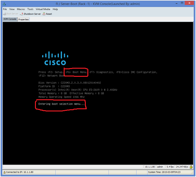
On the KVM console, press F6 to enter the boot menu.
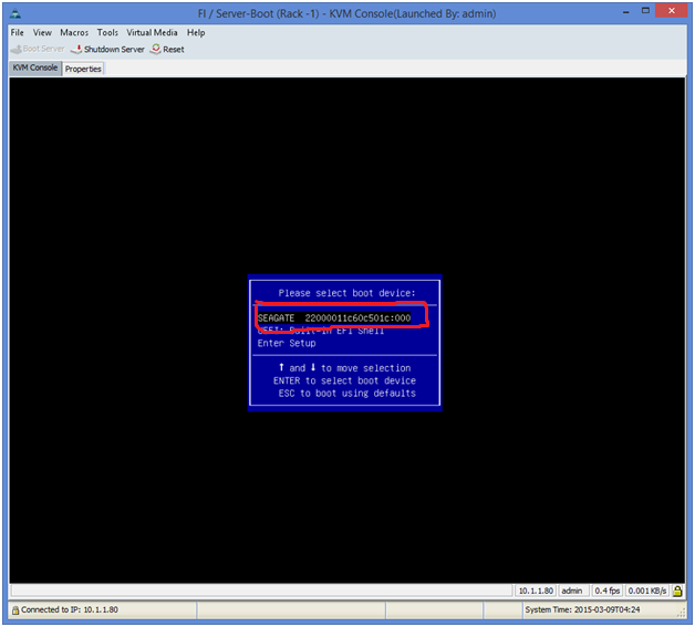
A Window will pop up with different media boot options. Notice the WWPN of the storage is one of them.
The server goes through the boot process and the ESXi is up and running.
 RSS Feed
